离岸价格
Get Latest Price|
- Minimum Order
国:
India
モデル番号:
-
离岸价格:
ロケーション:
-
最低注文量の価格:
-
最低注文量:
-
パッケージの詳細:
-
納期:
-
供給能力:
-
支払いタイプ:
-
製品グループ :
連絡先担当者 Vikash
Opposite Citi Mall, New Link Road, Andheri - West, Mumbai, Maharashtra
| 国: | India |
| モデル番号: | - |
| 离岸价格: | Get Latest Price |
| ロケーション: | - |
| 最低注文量の価格: | - |
| 最低注文量: | - |
| パッケージの詳細: | - |
| 納期: | - |
| 供給能力: | - |
| 支払いタイプ: | - |
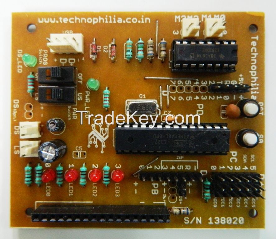
| 製品グループ : | Development Boards |


 Mother Board")


2GB RAM BPI M3 with WiFi&Bluetooth4.0 Open-source demo board Single Board Computer SBC")


