|
2)
APPLICATION
The cables are designed for areas where the integrity of the
electrical circuit is critical in maintaining power supply.
Applications can be found in emergency lightings, control and power
circuits, power stations, fire alarm systems, underground tunnels,
lifts, escalators, and high-rise buildings.
STANDARDS
Basic design to IEC ******1
FIRE PERFORMANCE
|
Circuit Integrity
|
IEC *******1; BS ***7 CWZ; DIN VDE *******4(FE**0);
CEI ****6/**1; SS****1; NBN C *****4 (cat. F3);
NF C*******2.3(CR1)
|
|
System circuit integrity
|
DIN ******2, E*0 depending on lay system
|
|
Flame Retardance (Single Vertical Wire Test)
|
EN ********2; IEC ********2; BS EN ********2;
VDE *********1 ; NBN C *****4 (cat. F1); NF C*******2.1(C2);
CEI ****5/**2; EN ********1*; DIN VDE ***********1*
|
|
Reduced Fire Propagation (Vertically-mounted bundled wires &
cable test)
|
EN *********4 (cat. C); IEC *********4; BS EN *********4; VDE
*********3; NBN C *****4 (cat. F2); NF C*******2.2(C1); CEI
****2/**4; EN ********4*; DIN VDE ***********4
|
|
Halogen Free
|
IEC ******1; EN ********1; DIN VDE ***********1;
CEI ****7/**1 ; BS *****1*
|
|
No Corrosive Gas Emission
|
IEC ******2; EN ********2; DIN VDE ***********2;
CEI ****7/**2 ; BS *****2*
|
|
Minimum Smoke Emission
|
IEC ******1&2; EN ****4 *1&2; DIN VDE
**********1&2;
CEI ****7/**1&2; EN ******1&2*; BS *****1&2*
|
|
No Toxic gases
|
NES *****3; NF C *****4
|
Note: Asterisk * denotes superseded standard.
VOLTAGE RATING
**0/**0 V
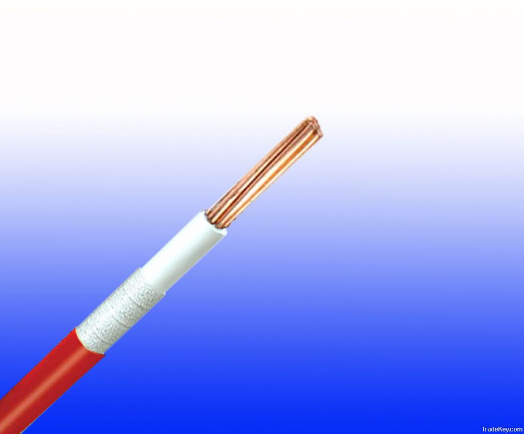
CABLE CONSTRUCTION
Conductor: Plain annealed copper wire, stranded according to
IEC(EN) ****8 class 2.
Insulation: Mica glass tape covered by extruded
cross-linked XLPE compound
Earth Conductor(optional): Uninsulated solid or stranded tinned
copper conductor.
Outer Sheath: Thermoplastic LSZH compound type LTS3
as per BS *****6.1 (Thermosetting LSZH compound type SW*-SW4 as per
BS *****2.6 can be offered.)
Physical AND THERMAL PROPERTIES
Temperature range during operation (fixed state): **0°C –
**0°C
Temperature range during installation (mobile state): **0°C –
**0°C
Minimum bending radius: 8 x Overall Diameter
Electrical PROPERTIES
|
Dielectric test:
|
***0 V r.m.s. x 5’ (core/core)
|
|
Insulation resistance
|
***0 MΩ x km (at *0°C)
|
|
Short circuit temperature
|
**0°C
|
CONSTRUCTION PARAMETERS
|
Conductor
|
FFX**0 *5mRZ*-R
|
|
Nominal Cross
Section Area
|
No./Nominal Diameter of Strands
|
Nominal Insulation Thickness
|
Nominal Sheath Thickness
|
Without Earth Conductor
|
|
Nominal
Overall Diameter
|
Approx.
Weight
|
|
mm2
|
No./mm
|
mm
|
mm
|
mm
|
kg/km
|
|
1.5
|
7/0.*3
|
0.5
|
0.5
|
4.4
|
*9
|
|
2.5
|
7/0.*7
|
0.5
|
0.5
|
4.9
|
*0
|
|
4
|
7/0.*5
|
0.5
|
0.5
|
5.5
|
*5
|
ElectricAl PROPERTIES
Conductor Operating Temperature : *0°C
Ambient Temperature : *0°C
Current-Carrying Capacities (Amp)
|
Conductor cross-
section
area
|
Reference Method 4 (enclosed in conduit in thermally insulating
wall etc)
|
Reference Method 3 (enclosed in conduit on a wall or in trunking
etc)
|
Reference Method 1 (clipped direct)
|
Reference Method *1 (on a perforated cable tray, horizontal or
vertical)
|
Reference Method *2 (free air)
|
|
Horizontal flat spaced
|
Vertical flat spaced
|
Trefoil
|
| Â |
2 cables, single-phase
a.c. or
d.c.
|
3 or 4 cables, *-phase a.c.
|
2 cables, single-
|
3 or 4 cables, *-phase a.c.
|
2 cables, single-phase
a.c. or
d.c. flat
and touching
|
3 or 4 cables, *-phase a.c. flat and touching or trefoil
|
2 cables, single
-phase
a.c. or
d.c. or flat and touching
|
3 or 4 cables, *-phase a.c. flat and touching or trefoil
|
2 cables, single-phase
a.c. or
d.c. or 3 cables three
phase
|
2 cables, single-phase a.c. or d.c. or 3 cables three phase
|
3 cables, trefoil *-phase a.c.
|
|
phase a.c. or d.c
|
|
1
|
2
|
3
|
4
|
5
|
6
|
7
|
8
|
9
|
*0
|
*1
|
*2
|
|
mm2
|
A
|
A
|
A
|
A
|
A
|
A
|
A
|
A
|
A
|
A
|
A
|
|
1.5
|
*8
|
*7
|
*2
|
*9
|
*5
|
*3
|
-
|
-
|
-
|
-
|
-
|
|
2.5
|
*4
|
*3
|
*0
|
*6
|
*4
|
*1
|
-
|
-
|
-
|
-
|
-
|
|
4
|
*3
|
*0
|
*0
|
*5
|
*6
|
*1
|
-
|
-
|
-
|
-
|
-
|
Voltage Drop (Per Amp Per Meter)
|
Nominal Cross
Section Area
|
2 cables d.c.
|
2 cables, single-phase a.c.
|
3 or 4 cables, *-phase a.c.
|
|
Ref. Methods 3 and 4 (enclosed in conduit etc, in or on a
wall)
|
Ref. Methods 1 and *1 (clipped direct or on trays touching)
|
Ref. Methods 3 and 4 (enclosed in conduit etc, in or on a
wall)
|
Ref. Methods 1,
|
Ref. Methods 1 and *1
|
|
*1 and *2 (in trefoil)
|
(Flat and touching)
|
|
1
|
2
|
3
|
4
|
5
|
6
|
7
|
|
mm2
|
mV/A/m
|
mV/A/m
|
mV/A/m
|
mV/A/m
|
mV/A/m
|
mV/A/m
|
|
1.5
|
*1
|
*1
|
*7
|
*7
|
*7
|
*7
|
|
2.5
|
*9
|
*9
|
*6
|
*6
|
*6
|
*6
|
|
4
|
*3
|
*2
|
*0
|
*0
|
*0
|
*0
|
|


 / ICEA S 87-640 CENTRAL LOOSE TUBE CABLE")


")


