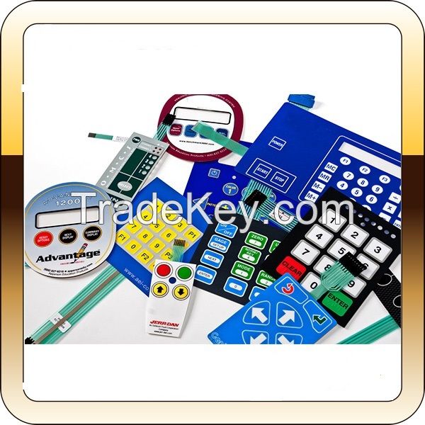
A membrane switch is a momentary switching device that is
manufactured by using a series of flexible layers of polymer films
and adhensives. The upper-most layer, called a graphic overlay, is
manufactured by printing on the second surface of clear polyester
or polycarbonate film. Membrane switches can be constructed with
multiple circuit layers, and more elaborate graphic design
features, such as domed key embossing. Designs that are more
complex require, more material layers for proper construction and
reliable operation. Membrane switches, when combined with
components such as a tactile dome, graphic overlay, or integrated
LEDs or resistors can provide the designer with virtually limitless
capablities to create the ideal custom user interface for their
products.
Technical
Specifications
Hot sale custom 2 membrane switch with 3M
adhesive and metal dome inside
|
Working Voltage |
≤*2VDC (*5 VAC) |
Life |
flat type≥1 million
times |
|
Working Current/Power |
**0MΩ **0V DC |
Stroke Switch |
0.1~0.4mm (no touching) |
|
Circuit Resistance |
*0Ω***0Ω( dependent on size and
layout) |
Recoil time |
≤*0ms |
|
The base pressure |
***0VDC |
Tail bending
performance |
≤**0° |
Features
1 Material PET(polyester),PC(polycarbonate)
2 Components: LED, metal dome, connector and circuit, all
these can be designed and made according to customer
requirements.
3 Dimension According to customer's demand,OEM service
4 Artwork Format CorelDraw, Adobe Illustrator AI or EPS,
AutoCAD Dwg or DXF
5 Color Pantone and RALcolor matching system.
6 Embossing raises the surface of graphic overlay to emphasize
the active key area,upper circuit can be embossed to insert metal
domes
Embossed type: Pillow emboss, Dome emboss, Frame
emboss
7 Keys Options For a tactile response and indicate the
location of switches
1. Tactile Keys: metal domes or poly domes
2. Non-tactile keys: flat , printed
silver spot on the circuit,
8 Cables is extension of circuit and communication with your
device
9 Circuitry option 1. Silver printed conductive
inks
2. Copper etched circuit /Polyimide Kapton circuit (
FPC)
3.PCB circcuit board
*0 Connector Tail 1.Zero insertion force(ZIF) with 0.5MM
,1.0MM,1.*5MM pitch
2. Female connector with 2.*4MM pitch;
3 .Male connector ;
4.Solder Pins
*1 Shielding For protection function
*2 Printing screen printing
*3 Window with clear or transparent window
*4 Surface glossy surface or matte surface
*5 Rear Adhesive
3M**7,3M**8,3M***0 ect