离岸价格
Get Latest Price|
- Minimum Order
国:
China
モデル番号:
-
离岸价格:
ロケーション:
-
最低注文量の価格:
-
最低注文量:
-
パッケージの詳細:
-
納期:
-
供給能力:
-
支払いタイプ:
-
製品グループ :

China
連絡先担当者 Mr. Wilson
6-703, FUYUAN COMMUNITY, YUFU ROAD, LONGGANG DISTRICT, SHENZHEN, CHINA, Muping, Sichuan
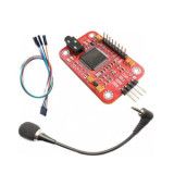
Voice
Recognition Module
Description:
We all know that
there is a kind of moule which can control the light on and off.
You make a sound, the light turns on. Then after a while it turns
off. This is not voice recognition. We may call it Sound Control.
Voice recognition is something that knows exactly what you were
saying.
We've beening thinking about a module which helps
to control other devices by voice and it will not cost too much.
Finally we designed this module. Well, what can this module do? It
can recognize as much as *5 voice instruction, which is suitable
for most cases involving voice
control.
Parameters:
1, Voltage:
4.**5.5V
2, Current: <*0mA
3, Digital
Interface: 5V TTL level UART interface
4, Analog
Interface: 3.5mm mono-channel microphone connector + microphone pin
interface
5, Size: *0mm X *7.5mm
This module can
store *5 pieces of voice instruction. Those *5 pieces are divided
into 3 groups, with 5 in one group. First we should record the
voice instructions group by group. After that, we should import one
group by serial command before it could recognize the 5 voice
instructions within that group. If we need to implement
instructions in other groups, we should import the group first.
This module is speaker independent. If your friend speaks the voice
instruction instead of you, it may not identify the
instruction.
Example
Here I will show you an
example how to control RGB by voice.
1.
Recording
We need to send serial command to this module.
You may need a USB-TTL module to connect it with PC. Send command
0xaa*1 to record. Please refer to the manual for more
information.
Please record the following voice instrctions
in order:
1, WHITE
2, RED
3,
GREEN
4, BLUE
5, OFF
Then send command
0xAA*1 to import group 1.
2. Hardware
connection
3. Code
Int redPin = *1; // R petal on
RGB LED module connected to digital pin *1
Int greenPin =
9; // G petal on RGB LED module connected to digital pin
9
Int bluePin = *0; // B petal on RGB LED module connected
to digital pin *0
Byte COM = 0; //reply from voice
recognition
Void setup()
{
Serial.
Begin(***0);
PinMode(ledPin, OUTPUT); // sets the ledPin
to be an output
PinMode(redPin, OUTPUT); // sets the
redPin to be an output
PinMode(greenPin, OUTPUT); // sets
the greenPin to be an output
PinMode(bluePin, OUTPUT); //
sets the bluePin to be an
output
Delay(***0);
Serial.
Write(0xAA);
Serial.
Write(0X*7);
Delay(***0);
Serial.
Write(0xAA);
Serial. Write(0X*1);
}
Void
loop() // run over and over again
{
While(Serial.
Available())
{
COM = Serial.
Read();
Switch(COM)
{
Case
0X*1:
Color(**5, **5, **5); // turn RGB LED on *-
white
Break;
Case 0X*2:
Color(**5, 0,
0); // turn the RGB LED red
Break;
Case
0X*3:
Color(0, **5, 0); // turn the RGB LED
green
Break;
Case 0X*4:
Color(0, 0,
**5); // turn the RGB LED blue
Break;
Case
0X*5:
Color(0, 0, 0); // turn the RGB LED
off
Break;
}
}
}
Void
color (unsigned char red, unsigned char green, unsigned char blue)
// the color generating
function
{
AnalogWrite(redPin,
red***2/**5);
AnalogWrite(bluePin,
blue***3/**5);
AnalogWrite(greenPin,
green***3/**5);
}
Upload the code above to
Arduino. Please disconnect TX and RX while uploading code because
uploading would occupy serial interface.
4. Result
Show
After uploading is done, connect RX and TX, and then
press RESET on Arduino.
You can see the video on
Youtube
Product list
1, Voice recognition Module
X1
2, Mic X1
3, 4 pin cable
X1
| 国: | China |
| モデル番号: | - |
| 离岸价格: | Get Latest Price |
| ロケーション: | - |
| 最低注文量の価格: | - |
| 最低注文量: | - |
| パッケージの詳細: | - |
| 納期: | - |
| 供給能力: | - |
| 支払いタイプ: | - |
| 製品グループ : | arduino board and accessories |


")


")
