FOB Price
Get Latest Price( Negotiable )
|Minimum Order
Place of Origin:
-
Price for Minimum Order:
-
Minimum Order Quantity:
1 Piece
Packaging Detail:
carton
Delivery Time:
20days
Supplying Ability:
500 Piece per Month
Payment Type:
T/T, Western Union
連絡先担当者 john
1605, Building 12, Dingtai Fenghua Phase 6, Qianhai Road, Shenzhen, Guangdong

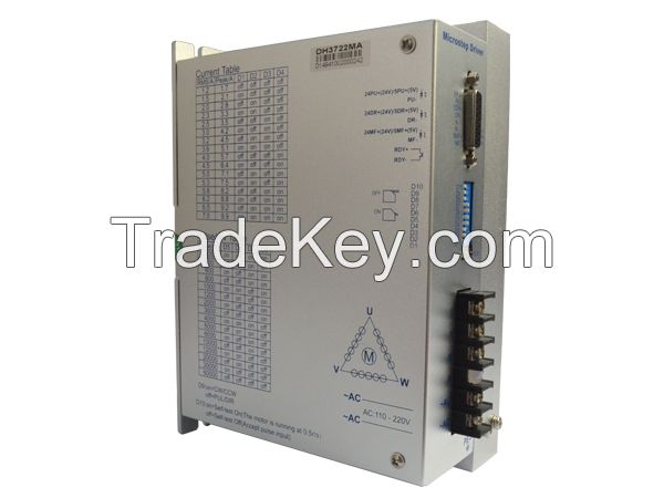
| IM(A) | 1.2 | 1.5 | 2.0 | 2.3 | 2.5 | 3.0 | 3.2 | 3.6 | 4.0 | 4.5 | 5.0 | 5.3 | 5.8 | 6.2 | 6.5 | 7.0 |
| D1 | OFF | ON | OFF | ON | OFF | ON | OFF | ON | OFF | ON | OFF | ON | OFF | ON | OFF | ON |
| D2 | OFF | OFF | ON | ON | OFF | OFF | ON | ON | OFF | OFF | ON | ON | OFF | OFF | ON | ON |
| D3 | OFF | OFF | OFF | OFF | ON | ON | ON | ON | OFF | OFF | OFF | OFF | ON | ON | ON | ON |
| D4 | OFF | OFF | OFF | OFF | OFF | OFF | OFF | OFF | ON | ON | ON | ON | ON | ON | ON | ON |
| D9 |
OFF:PU+DIR pulse
mode ON:CW/CCW pulse mode;note:set the mode after power off |
| D10 |
OFF: receive external
pulse ON: self-test ,after power on ,the motor run with 30RPM |
| Pu/Rev | 400 | 500 | 600 | 800 | 1000 | 1200 | 2000 | 3000 | 4000 | 5000 | 6000 | 10000 | 12000 | 20000 | 30000 | 60000 | |
| D5 | ON | OFF | ON | OFF | ON | OFF | ON | OFF | ON | OFF | ON | OFF | ON | OFF | ON | OFF | |
| D6 | ON | ON | OFF | OFF | ON | ON | OFF | OFF | ON | ON | OFF | OFF | ON | ON | OFF | OFF | |
| D7 | ON | ON | ON | ON | OFF | OFF | OFF | OFF | ON | ON | ON | ON | OFF | OFF | OFF | OFF | |
| D8 | ON | ON | ON | ON | ON | ON | ON | ON | OFF | OFF | OFF | OFF | OFF | OFF | OFF | OFF | |
| Name | function | description |
| PWR | Power light | When power on ,the green light is on |
| ALARM | Over current/under voltage/over voltage displaying light | If the drive Over current/under voltage/over voltage, the red light is on |
| 24PU+ | 24Vpulse input VCC | Connect to 24V pulse VCC (support PLC 24V+ ) |
| 5PU+ | 5V pulse input VCC | Connect to 5v pulse VCC |
| PU- | Pulse input negative |
Pulse signal: In single pulse
(pulse/direction) mode, this input represents pulse signal, each
falling edge active. In CW/CCW pulse mode,5PU and PU- are CW input |
| 24DR+ | 24V direction input VCC | Connect to 24V pulse VCC (support PLC 24V+ ) |
| 5DR+ |
5Vdirection input
VCC |
Connect to 5v pulse VCC |
| DR- | Direction input negative |
DIR signal: In single-pulse
mode, this signal has low/high voltage levels, representing two
directions of motor rotation; In CW/CCW pulse mode,5DR and DR- are CCW input |
| 24MF+ | 24V enable input VCC | Connect to +24V signal power supply |
| 5MF+ | 5V enable input VCC | Connect to +5V signal power supply |
| MF- | Enable input negative | Enable signal: This signal is used for enabling/disabling driver. High level for enabling the driver and low level for disabling the driver. Usually left UNCONNECTED (ENABLED). |
| RDY+ | Drive ready signal output VCC | Drive ready output signal ,if no fault,this output is off ,if fault,the output is on .after power on ,the alarm light will be on 10ms,and the RDY+/RDY will be on too (10ms) |
| RDY- | Drive ready signal output negative | RDY+,RDY- output current is 50MA,the max voltage is 50VDC |
| AC | AC power supply input | AC110-220V,the max input power is AC240V |
| N | NC | |
| U | Motor U | Motor U, |
| V | Motor V | Motor V |
| W | Motor W | Motor W |


 Automation Co, .lt")