FOB Price
Get Latest Price( Negotiable )
|Minimum Order
Place of Origin:
-
Price for Minimum Order:
-
Minimum Order Quantity:
1 Piece
Packaging Detail:
carton
Delivery Time:
20dyas
Supplying Ability:
500 Piece per Month
Payment Type:
T/T, Western Union
連絡先担当者 john
1605, Building 12, Dingtai Fenghua Phase 6, Qianhai Road, Shenzhen, Guangdong

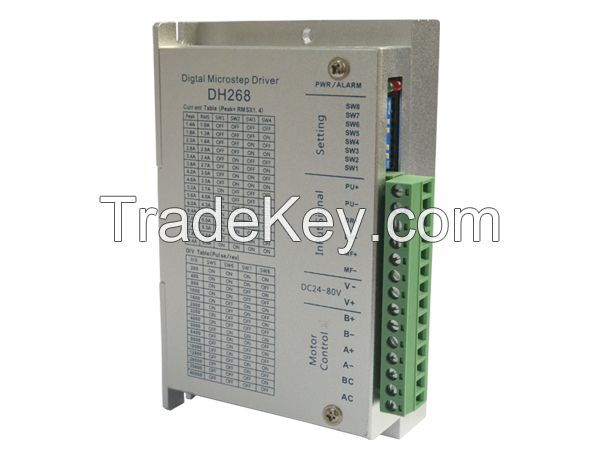
| Peak current(A) | RMS current (A) | SW1 | SW2 | SW3 | SW4 |
| 1.4 | 1.0 | OFF | OFF | OFF | OFF |
| 1.8 | 1.3 | OFF | OFF | OFF | ON |
| 2.2 | 1.6 | OFF | OFF | ON | OFF |
| 2.8 | 2.0 | OFF | OFF | ON | ON |
| 3.4 | 2.4 | OFF | ON | OFF | OFF |
| 3.8 | 2.7 | OFF | ON | OFF | ON |
| 4.2 | 3.0 | OFF | ON | ON | OFF |
| 4.6 | 3.3 | OFF | ON | ON | ON |
| 5.2 | 3.7 | ON | OFF | OFF | OFF |
| 5.6 | 4.0 | ON | OFF | OFF | ON |
| 6.0 | 4.3 | ON | OFF | ON | OFF |
| 6.4 | 4.6 | ON | OFF | ON | ON |
| 7.0 | 5.0 | ON | ON | OFF | OFF |
| 7.4 | 5.3 | ON | ON | OFF | ON |
| 7.8 | 5.6 | ON | ON | ON | OFF |
| 8.4 | 6.0 | ON | ON | ON | ON |
| Pul/rev | SW5 | SW6 | SW7 | SW8 |
| 200 | ON | ON | ON | ON |
| 400 | ON | ON | ON | OFF |
| 800 | ON | ON | OFF | ON |
| 1000 | ON | ON | OFF | OFF |
| 1600 | ON | OFF | ON | ON |
| 2000 | ON | OFF | ON | OFF |
| 3200 | ON | OFF | OFF | ON |
| 4000 | ON | OFF | OFF | OFF |
| 5000 | OFF | ON | ON | ON |
| 6400 | OFF | ON | ON | OFF |
| 8000 | OFF | ON | OFF | ON |
| 10000 | OFF | ON | OFF | OFF |
| 12800 | OFF | OFF | ON | ON |
| 20000 | OFF | OFF | ON | OFF |
| 25600 | OFF | OFF | OFF | ON |
| 40000 | OFF | OFF | OFF | OFF |
 4ã€Interface
description
4ã€Interface
description
| Name | function | description |
| PWR | Power light | When power on ,the green light is on |
| ALARM | Over current/under voltage/over voltage displaying light | If the drive Over current/under voltage/over voltage, the red light is on |
| PU+ | Pulse input positive |
Pulse signal: In single
pulse (pulse/direction) mode, this input represents pulse signal,
each falling edge active; 4-5V for High -level, 0-0.5V for
low-level Series connect resistors for current-limiting when +12V or +24V used.(should connect 1k resistor for +12V,2k for +24V) |
| PU- | Pulse input negative | Pulse signal: In single pulse (pulse/direction) mode, this input represents pulse signal, each falling edge active; 4-5V for High -level, 0-0.5V for low-level |
| DR+ | Direction input positive |
DIR signal: In single-pulse
mode, this signal has low/high voltage levels, representing two
directions of motor rotation; Series connect resistors for current-limiting when +12V or +24V used.(should connect 1k resistor for +12V,2k for +24V) |
| DR- | Direction input negative | DIR signal: In single-pulse mode, this signal has low/high voltage levels, representing two directions of motor rotation; |
| MF+ | Enable input positive |
Enable signal: This signal is
used for enabling/disabling driver. High level for enabling the
driver and low level for disabling the driver. Usually
leftUNCONNECTED
(ENABLED). Series connect resistors for current-limiting when +12V or +24V used.(should connect 1k resistor for +12V,2k for +24V) |
| MF- | Enable input negative | Enable signal: This signal is used for enabling/disabling driver. High level for enabling the driver and low level for disabling the driver. Usually leftUNCONNECTED (ENABLED). |
| V- | Power input COM | DC24-80V |
| V+ |
Power input VCC |
|
| A+,AC,A- | Motor A phase | Connect to Motor A phase, AC connect to the motor A phase middle lead |
| B+,BC,B- | Motor B phase | Connect to Motor B phase, BC connect to the motor B phase middle lead |


 Automation Co, .lt")